The Software in Laser Light Math
After examining this site’s hardware section, you can understand that Laser Light Math requires some workable control software. Most importantly, this software must provide a convenient interface for the laser artist who wants to compose and structure images and build laser light shows. If you have worked around stage lighting, you know that most stage lighting computers provide this control mechanism with computer software interfaces. Many of these interfaces run well on high-speed laptop computers. In those systems, lighting levels, time fades, and the internal structure of those time fades, are all composed by using a simple mouse and keyboard commands. Early in the world of computer controlled stage lighting systems, these artistic elements were set primarily with a large manual board with actual mechanical faders that were connected to an internal computer and memory capture/playback system. Computerized stage lighting systems have, fortunately, grown ever more sophisticated and compact over the years. Having worked with many of these systems in my career as a stage lighting designer, I have come to admire how easily they capture data and how precisely they can play those data back. Similarly, I remember the early electronic music synthesizer systems that were very useful tools for composing and playing back complex musical structures. For me, creating a control console for lasers calls for a computer and software arrangement that can incorporate both of these worlds, the world of modern stage lighting control and the world of electronic music control. With this goal in mind, I started by designing a functional graphical user control interface for the Laser Light Math hardware. Remember, Laser Light Math requires three lasers, three X/Y galvanometer-scanning units, and an eight-channel polychromatic optical modulator (PCAOM) system, and a fair amount of additional support hardware as well. There is a lot of analog and digital activity here, and it has to be carefully controlled. The control oscillators, for example, require 12 bits of digital resolution, and all of the amplifier circuits are 8 bits wide.
After considering different software approaches, I settled on Visual Basic 6.0 as my primary code shaping platform. Visual Basic is relatively easy to use and to master. If you have ever programmed in the older Basic environments, you will quickly recognize many of the ancient commands and their respective code structures. But, especially important, VB contains wonderful tools for shaping and organizing numerous visual graphical tools. I toyed with using Visual C+, which would have produced even better compiled code, but in the end I settled on Visual Basic because of how easy it is to use and learn. So the entire software control package was written in VB 6.0, about 200 pages of code, and then compiled into efficient native code. The interface is quite fast and works well.
In order to make a laptop computer communicate with the Laser Light Math hardware, a serial interface had to be constructed that would rapidly transport data from the laptop to the hardware devices. Interestingly, Visual Basic is not generally used to control mechanical or electronic devices, but, with a little creative wit, it can made to do so if you incorporate a tool that is available from Microsoft. This free tool is the MSComm control for Visual Basic and can be quickly downloaded. Specifically, the fancy title for the control is MSCOMM32.OCX. I believe some versions of Visual Basic and C+ include the tool with the primary software package, but older version did not have it (or at least I could not find it). So, I downloaded it from the Microsoft site.
MSComm gives you access to a fast serial RS232 output in your Visual Basic code. With it, you can write control code that will send your data down a 115 Kilobaud RS-232 connection. This is fast enough for the Laser Light Math hardware to work properly.
In addition to the MSComm link, the Laser Light Math system requires a serial RS232 to DMX-512 transceiver. I decided to use the standard DMX-512 interface because it would allow me to connect my system to many stage lighting computers that use this common serial interface protocol. Additionally, a DMX-512 interface allows stable serial transmission over very long lines. It is a reliable standard interface format in stage lighting and electronic music.
For the RS-232 to DMX-512 converter box (transceiver), I used a unit made by JPK Electronics in New Zealand. JPKL makes two versions of this box, one works with RS-232, and the other with USB 2.0. To use the USB box, however, you need to load a virtual serial (COM) port, not difficult but sometimes a little frustrating. Also, the USB version manufactured by JPK did not seem to work as reliably as the RS-232 unit. Could just be my stuff, and not their hardware though.
Using the JPK RS-232 to DMX-512, made writing the code in Visual Basic relatively easy. This is because the JPK unit employs an easy to understand and workable ASCII character based communications protocol. Sending the ASCII combination C000L255, for example, will set channel 1 to a binary level of 255. If you want to know more about how this ASCII interface works, go ahead and download the instruction manual from the JPK site. The manual pretty much explains it all.
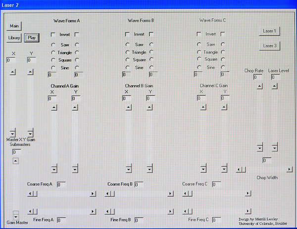
The first task in writing the Laser Light Math control panel software was to develop a screen or graphic interface that would allow me to control each laser with a mouse device. Here is a photo of a laser control screen (there are three of these screens in the complete software package, one for each laser).
.
By using the control elements in this screen, the laser artist can set the
laser’s light amplitude, the control frequencies for X and Y axis arrangements,
select specific wave forms, and much more. Note that the screen incorporates
three X/Y axis control modules. Outputs from these three modules are summed
together into a final composite signal (an amazingly complex signal when viewed
on an oscilloscope). Also note that you can select various waveform shapes for
each axis (sine, cosine, square, triangle, and saw tooth). With this range of
waveform combinations, it is possible to create some incredibly complex images,
images that go way beyond the capability of most spirograph devices. A final
section on this screen is the “chopping” control. This module allows
the laser artist to turn the laser on and off from 0 to 10,000 times per second.
Additionally, this control allows the user to vary the pulse-width of the chopped
output. Being able to chop the laser light beam adds considerable artistic flexibility
to the shaping of output images. Once an image has been created that the laser
artist wants to keep, it can be saved in a library.
The library module looks like this:
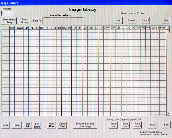
The library is an especially important tool for the laser artist because it becomes a place to store and archive images in disc memory. These stored images can be called upon later when the designer assembles a “show” where multiple images can modified and manipulated through fade and dissolve sequences. For the purposes of Laser Light Math, a base library containing over a hundred images was assembled. These images relate to fundamental roulette and spirograph patterns. Each image can be loaded into the show and manipulated or modified for effect. Once the image has been properlyh set for the show, it can be stored in memory and/or on disc as part of a cue. For ultimate backup, shows are saved to floppy disc or to the hard drive as separate files. The library has its own memory space on the hard drive, but can be backed up on floppy or CD. Having numerous library files is allowed.
Cues in a Laser Light Math show can be rather complex, with three lasers fading up and down at the same time. Generally, each cue incorporates all three lasers, but it does not need to do this. You can have cues that move or change just one or two lasers. It is entirely up to the laser artist composing the show.
Here is the actual “playback” or “show” screen. During a peformance or show, this is where the laser artist will be spending most of his/her time..
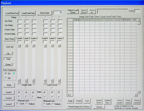
Study this screen and you will see that fade times are set with mouse controls with related sliders. Additionally, the operator can select, via buttons, differing fade patterns that incorporate lead and lag fade times. And, of course, fades can be coupled together so that they run sequentially without stopping. This is all done with the mouse controls by moving the various faders and selecting appropriate buttons and then storing the show. When set, the show can be saved, archived, and recalled for performance. Of course, as a lighting designer, and for obvious reasons relating to "anything can happen" events, I always want the ability to intercept the computer control and run it manually. You can do this by simply clicking on certain buttons on the playback or show panel.
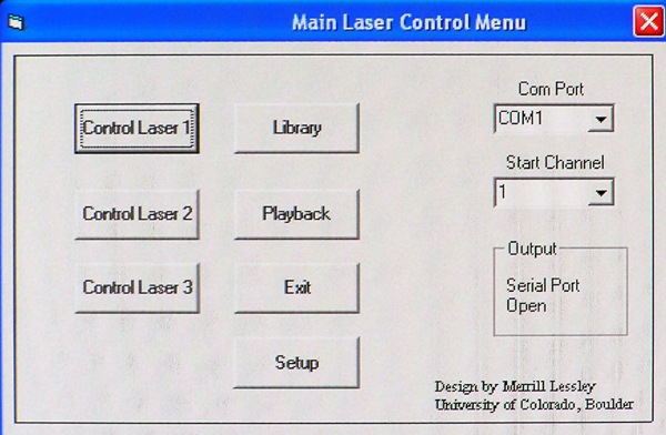
The last screen utilized by Laser Light Math is the opening or home screen. This screen lets the user set the protocol for the serial interface and provides information regarding the success of that connection. The operator can go to any of the other screens from this menu by just clicking on a respective button. Naturally, this ability to maneuver between screens is included in all other screens, allowing access to any other screen from within the current screen.
A compiled version of the Laser Light Math software is available upon request. Compiled in native code, the package runs in Windows 98B, Windows 2000, and in XP. I have no MAC version; I’m sorry about that. If you want a copy of the compiled software, just send an email to me (lessley@colorado.edu) and I will see that you receive a copy. I will also send you a library and a short sample show. You can load the package and try its various features. Unfortunately, you will not be able to project laser images without the Laser Light Math hardware, but you can see how the interface works in general.