Price Research Group
Quantum Dynamics with a side of Acoustics
at the University of Colorado Boulder
Flute Acoustics
Linear Response of the Recorder Air-Jet Amplifier
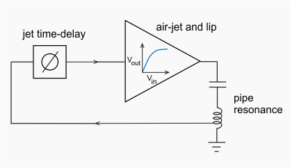
In flute-family musical instruments, oscillations of an acoustic resonator are driven by an air-jet, formed either by a fixed duct or by the variable geometry of a player's lips. Quantitative models of flute drive mechanisms first appeared in the 1960's and have been continuously developed since then. The instrument is usually viewed as a feedback oscillator, closely analogous to an electronic feedback oscillator, as sketched here. Gain is provided by growth of an unstable sinuous mode on the air-jet, which interacts with a sharp edge or lip to create a hydrodynamic flow with a strong periodic component. This flow drives an acoustic oscillation in the pipe, and the resulting acoustic flow disturbs the jet near where it emerges from the duct, thus seeding the unstable sinuous mode and closing the feedback loop. Time delay around the loop is mainly due to propagation of the sinuous mode on the jet at a velocity of order 10 m/s. Saturation of the air-jet amplifier provides the non-linearity necessary for the feedback oscillator to maintain a stable amplitude.
The goal of our experiments is to test the predictions of a lumped flute drive model under the simplest possible conditions. Instruments with a fixed duct geometry, where the blowing pressure is the only jet control parameter, are simpler than those, such as the transverse flute, where the duct is formed by the player's lips. Among the duct-flutes, the recorder has been a popular choice for flute research because the jet is laminar under most playing conditions, a simpler case to model than a turbulent jet. It is also readily available in a range of sizes with highly standardized geometry.
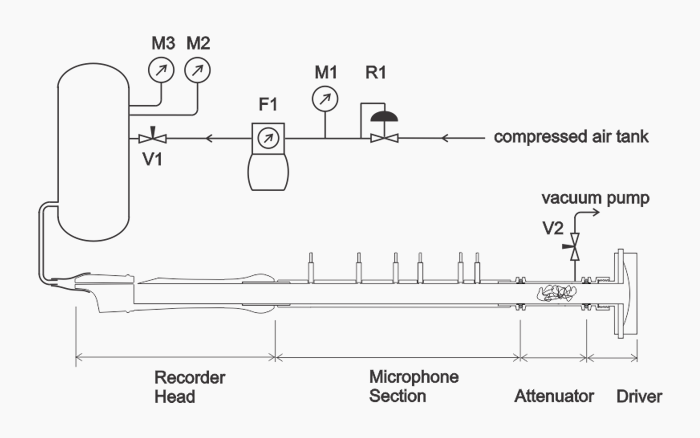 The figure above shows our apparatus, a Yamaha tenor recorder head connected to a waveguide reflectometer and a blowing system. The blowing pressure is controlled by valve V1 and the jet flow is measured by flow meter F1. The six microphones measure the right and left traveling acoustic wave amplitude and phase in the waveguide. Valve V2 is used to sink any mean flow in the waveguide that comes from the portion of the jet flow split below the lip.
"Linear-response reflection coefficient of the recorder air-jet amplifier," John. Price, William A. Johnston, Daniel D. McKinnon arXiv:1502.02170.
Slides (2.3 MB pdf) from the October 2014 ASA meeting.
